With a 75 kvp Exposure the Peak of the Curve on the Continuous Emission Spectrum is Approximately
Effect of Changing X-ray Tube Voltage (kV)

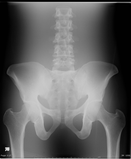
In screen film radiography, the choice of x-ray tube voltage (kV) affected the image contrast; this is no longer the case for any digital radiographic system. In this example, images were obtained of a pelvic phantom at three kV values using a commercial computed radiography (CR) imaging plates. All exposures were performed using phototiming. This image was generated at 60 kV, and required a relatively high radiation intensity of 141 mAs. The S number generated by the system was ~140, which corresponds to an average air kerma incident on the imaging plate of the order of 7 mGy. The L number generated by this imaging system was 2.3, which means that the range of intensities incident on the plate differed by a factor of 200 or so (10^2.3 ~ 200). The skin dose for this examination was estimated to be 7.6 mGy; for a given irradiation geometry and x-ray system, the factors that affect the skin dose are the kV and mAs that are used to generate the image.

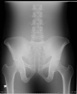
The image shown above was generated at 75 kV and required an exposure of 36 mAs. The increase in x-ray tube voltage increases the amount of radiation coming out of the x-ray tube, as well as the average photon energy (i.e., increased penetration). Accordingly, the tube current exposure time product value (mAs) is reduced to 36 mAs; whereas at 60 kV, the value was much higher (141 mAs). The resultant S number generated by the CT system was ~ 150, indicating that the average radiation incident on the imaging plate was very similar to the value for the image generated at 60 kV; this is to be expected because the images were obtained using phototiming, where the exposure time is determined automatically (i.e., when the imaging plate has received the correct exposure). The L value for this image was 2.1, showing that increasing the x-ray tube voltage from 60 reduced the dynamic range from 200:1 at 60 kV to 125:1.
Note that the image appearance at 75 kV is very similar to that obtained at 60 kV; differences in dynamic range are compensated for using different display windows. Images at lower kVs, which have a wide dynamic range, must use a wider window; increasing the kV reduces the dynamic range, but permits the use of narrower display windows. As a result, images obtained at different kV values, and the same intensity at the imaging plate, will have very similar appearance. The skin dose is now 3.2 mGy, which is lower than the 7.6 mGy associated with the radiograph taken at 60 kV. For a more penetrating beam, less radiation is required at the patient entrance to achieve the required intensity at the imaging plate (i.e., 7 mGy).

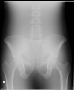
The image shown above was generated at 120 kV and required an exposure of only 6 mAs. This is much lower than the mAs whereas at 60 kV (141 mAs) and 75 kV (36 mAs). The resultant S number generated by the CR system was ~ 160, again indicating that the average radiation incident on the imaging plate was very similar to the value for the image generated at 60 kV and 75 kV, because of the use of phototiming. The L value for this image was 1.8, corresponding to a dynamic range of 60:1; it is generally true that increased kV values, corresponding to more penetrating x-ray beams, will reduce the dynamic range of the detected x-ray beam intensities at the image receptor. Note that the image appearance at 120 kV is similar to those at 60 kV and 75 kV. Differences in dynamic range are generally compensated for using different display windows. The skin dose is now much lower at 1.4 mGy, which is lower than the 7.6 mGy associated with the radiograph taken at 60 kV. Although increasing kV will always reduce the patient dose, this also increases the amount of scatter in the image (see below).
Source: https://www.upstate.edu/radiology/education/rsna/radiography/kvp.php